My Gate is Not Closing - Alignment of Photo Eye Sensors for Gate Operators
Troubleshooting (Close) Photo Eyes
When the Gate is not closing, the sensors may be blocked or misaligned. Learn how to unblock and align Photo Sensors (Eyes) for Close Eye or Interrupt Circuit issues. These sensors ensure safety by preventing the gate from closing when an object is detected in its path. If the sensors are blocked or unaligned, the gate will not close.
Symptom: The gate is not closing, and the main control board displays the following diagnostic codes: 61, 64, 70, or 73. Either the Close Eye/Interrupt or Eye Only LEDs will be lit.
Resolution: Unblock or align sensor (eye).
Identify and Locate the Photo Sensors (Eyes):
- The photo sensors will be mounted across the opening of the driveway and are at least 4 inches off the ground.
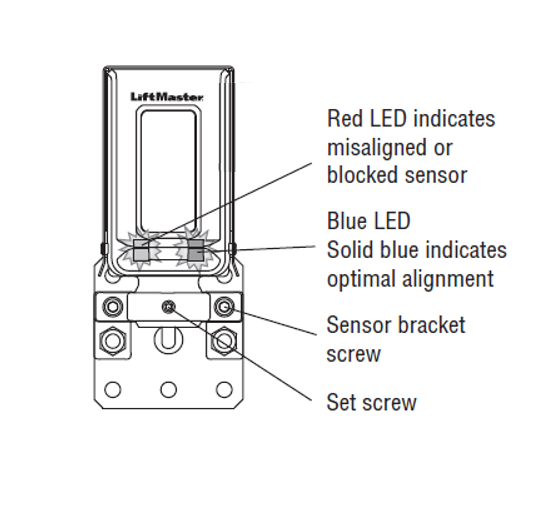
- Look for small rectangular hooded boxes, approximately 3" wide by 5" tall.
- LMRRUL - Retro-Reflective: A combined sensor that sends and receives a signal back and forth across the driveway. You'll see a reflector on it.
- LMTBUL - Through Beam: Has two sensors; one sensor sends a signal across the driveway and the other sensor receives the signal.
Locate the receiver's eye below the window face. There will be a red or blue LED light. The LED color will determine if the photo eye is aligned.
- Red LED- Power is on, but the sensor is misaligned or blocked.
- Solid Blue LED - The sensor is aligned, and ready to close the gate.
- Blinking Blue LED - The Sensor is almost aligned. Slow blinking means the signal is weak; fast blinking means the signal is strong.
How to Adjust the Sensor Eye:
- Attempt to move the housing (case) of the sensor eye.
- If the housing doesn’t move, remove the Wire Cover to expose the Set Screw and Sensor Bracket, shown above. Tools needed: Phillips Head #2 Screwdriver and two Allen Keys, sizes 3/32' and 5/32'.
How to Remove the Wire Cover:
- Remove the two Philips head screws located on either side of the wire cover box.
- Loosen the two sensor bracket screws using the 5/32' Allen key (do not remove them).
- Adjust the housing until the LED on the face is solid blue.
- Once the LED is solid blue, the sensor eye is aligned. Retighten the sensor bracket screws.
- Check the very small set screw in the middle of the bracket. Tighten, if needed, using the smaller 3/32' Allen key.
- Reinstall the Wire Cover.
If the gate operator doesn't close or completely function correctly, or the Photo Eye LED doesn't stay Solid Blue, contact a local servicing professional for additional assistance.
Find Help By Product 

View More Brands
